Terminus: talking past a flaring red star
Proposal section 6: the loudest thing in the sky
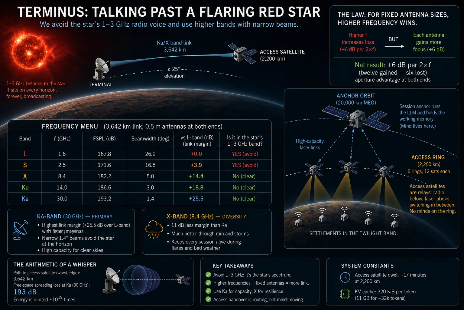
Someday, generations from now, a curious mind in the twilight band will build the first radio receiver from copper wire and patience, sweep it across the dial, and make a discovery that would break a terrestrial radio pioneer's heart: the sky is radio-loud, and the source is their gentle red sun, the fixed lamp on the horizon. Red dwarfs of its kind crackle with flares and, worse, emit organized, coherent radio bursts — brightest across roughly 1 to 3 gigahertz, the very range where radio is easiest to build. On Earth those frequencies carried the first satellite phones and navigation beacons. Here they belong to the star, which sits on every horizon, forever, transmitting.
Every link in our architecture — terminal to wheel, wheel to anchor — is a radio or laser beam sharing the sky with that voice. This section chooses the frequencies, and the choice starts with understanding just how faint a satellite whisper is.
The arithmetic of a whisper
A radio transmission spreads like paint on an expanding balloon: by the time the wavefront reaches a satellite, the energy that left the antenna is smeared across a sphere thousands of kilometers wide, and the receiver catches only the fleck that lands on it. This section has to put a number on that fleck, and the number is so small that ordinary notation gives up first. So, two tools before the physics: a unit built for multiplying, and a derivation short enough to check by hand.
Decibels: a unit for multiplying
A decibel (dB), which
the altitude survey borrowed for one column,
is ten times the base-ten logarithm of a power ratio: 10 dB is a factor of ten, 20 dB a factor of a hundred, and
3 dB — near enough — a factor of two. Ratios are scored in logarithms
because a radio link is a chain of multiplications — spread by this much,
focus by that much, lose a little to rain — and logarithms turn the chain
into a sum. The whole trade study below is additions and subtractions of
dB. One convention to watch: when the thing being doubled is a distance
or a frequency rather than a power, it enters the power ratio squared,
so its term reads 20·log₁₀ instead of 10·log₁₀. Both appear shortly.
Step one: the balloon
Strip the antennas away and let an idealized
bare wire radiate its power P equally in every direction. At distance
d that power has been smeared over a sphere of area 4πd², so the
power crossing each square meter of sky is P / 4πd². Double the
distance and each square meter gets a quarter of the power; triple it
and each gets a ninth. This is geometry and nothing else. Frequency has not entered.
Step two: the catch
A receiving antenna takes power from the
passing wave in proportion to the area it presents — its effective
aperture. The reference receiver that every path-loss table assumes is
that same idealized wire, and its effective aperture turns out to be
λ²/4π. That constant is worth deriving rather than accepting, because
it is the only place frequency enters the whole derivation — and the
route to it passes through the one thing a wave cannot help doing.
Why every beam fans out
Send a transmission out through any face of width D — a dish, a slit
in a wall — and it refuses to stay a parallel-sided beam. It fans out,
and the reason takes four short steps.
Every point is a source. Picture the face as a row of tiny emitters side by side, each launching the same ripple at the same instant, like a row of pebbles dropped into a pond together. A listener far away, in any direction, receives the sum of all those ripples.
Straight ahead, they agree. Directly in front of the face, every ripple travels the same distance, so they all arrive in step: crest on crest, trough on trough. They add up, and that direction is bright.
Off to the side, the trips differ. Look a little to one side instead.
Now a ripple from the far edge of the face has farther to go than one
from the near edge — about D times the angle, in radians, farther. A
ripple that travels farther arrives later in its cycle. Half a
wavelength of extra trip turns an arriving crest into a trough; a whole
wavelength brings it back around to a crest, exactly one cycle late.
Every point on the face still fires in step. Only the length of the trip
puts the ripples out of step.
One wavelength edge to edge, half between partners: they cancel. You may know the rule for two waves: if one travels half a wavelength farther than the other, a crest meets a trough and the two wipe each other out. That rule does the work here too. But a face is not two antennas; it is a whole row of them, and for the face to go dark, every point on it needs a partner to cancel.
Keep looking farther to the side until the far edge's extra trip is
exactly one wavelength. The points in between fall behind by in-between
amounts: a point in the middle of the face is half a wavelength behind
the near edge, and a point a quarter of the way across from the near
edge is a quarter of a wavelength behind. Now pair each point with the
one half a face-width away from it. Their trips always differ by half a
wavelength, so one arrives as a crest exactly when the other arrives as
a trough, and the two cancel. Every point has such a partner, so the
whole face cancels, and that direction is dark. It sits where D times
the angle equals one wavelength: at an angle of about λ/D radians.
Why not stop sooner, when the two edges differ by half a wavelength? Then the two edges cancel each other, but little else does. The middle of the face is only a quarter of a wavelength behind the near edge, too little to cancel anything, and most of the points across the face still arrive roughly together. Think of a crowd clapping slightly out of time: the claps smear, but they still add up to a roar. At that angle the face is dimmer, about two-thirds of its straight-ahead strength, but far from dark. Only when the lag across the face reaches a whole wavelength is it spread evenly over one full cycle, so that for every crest arriving there is a trough arriving with it.
Between the bright center and the dark edges the cancellation is only partial, so the brightness fades smoothly from one to the other. That fan of brightness is the beam. A wider face piles up a full wavelength of extra trip at a smaller angle, so its dark edges close in; a longer wavelength needs a bigger angle, so they spread out. Narrower faces and longer wavelengths fan wider. This is diffraction, the signature move of everything wavelike, and it sets a floor under how tightly any antenna can focus.
The simulator states the dark edge in one line, and its tests pin the angles the figure below reads out:
/// First null (rad) of a uniformly lit straight-edged face of `width` (m) at
/// `frequency` (Hz): `sin θ = λ/D`. `None` for a face narrower than one
/// wavelength, which has no dark direction at all.
pub fn first_null_rad(width: f64, frequency: f64) -> Option<f64> {
    let ratio = (SPEED_OF_LIGHT / frequency) / width;
    (ratio <= 1.0).then(|| ratio.asin())
}
A round dish goes dark a little farther out, at about 1.22·λ/D; a
straight-edged face, the one-slice picture drawn here, goes dark at
exactly λ/D. The figure's glow comes from a companion function,
line_array_factor,
which adds up the ripples from every point on the face in each
direction, and
a test
checks that the glow falls to zero exactly at first_null_rad.
Why a wider face makes a narrower beam
In the figure below, the yellow segment is the far edge's one wavelength of extra trip toward the dark edge. The two yellow dots are one canceling pair, half a face apart, stepping across the face; dotted lines carry each one's extra trip onto the segment, where the two marks always sit half a wavelength apart. Drag the width and watch the dark edges close in:
The wave is slowed enormously for the eye; the angles are honest. The glow is where the power goes, and it fades to black on the dotted edges. Every point fires in step; the only thing that puts ripples out of step is the length of the trip. Whatever the width, the far edge's extra trip toward the dark edge is one wavelength, so the lit pair's two marks on the yellow segment always sit half a wavelength apart: crest against trough. The shaded triangle is a ramp that climbs one wavelength across the face; its angle at the near edge, marked ≈ λ/D, is the dark edge's angle. Widen the face and the same climb spreads over a longer ramp, so it flattens. The construction is drawn for one dark edge at a time. Flip to Left edge to see the mirror image, with the right edge of the face as the far edge: the same angle on the other side, so the beam spans about 2λ/D from dark edge to dark edge. The strip under the scene is what a listener far away hears: the two dots of the lit pair, and the whole face added up. Move the listener with Listen: straight ahead everything adds; with the edges half a wavelength apart the face is dimmed but far from dark; at the dark edge the pair trace mirror images and the face goes flat; past it, at one and a half wavelengths, a faint sidelobe returns, about a fifth as strong: the face splits into thirds, two cancel each other, and the third left over adds to two-thirds of its own strength. Press Reveal sidelobes to brighten the faint glow on a decibel scale; the real power there is 1/22 of the beam's. Only the ratio D/λ matters, so a shorter wave does exactly what a wider face does. A half-meter dish is about 2.7 wavelengths across at L-band, near the left end of the slider; at Ka it is 50, far off the right end, and its beam is a pencil. In beams, not blankets these same ripples come back as a phased array and learn to steer.
Drag the face width and watch the yellow segment. Its length never changes; it is always one wavelength. What changes is its lean. Together with the face and the dashed line, it forms a thin right triangle. The dashed line is a ramp, and the yellow segment is how high it must climb: exactly one wavelength over the length of the face. On a face two wavelengths wide, the ramp is short and the climb steep: 30 degrees. Stretch the face to four wavelengths, and the same one-wavelength climb spreads over twice the distance, so the ramp flattens to about 14.5 degrees; at twelve wavelengths, it is under 5. The ramp lies at right angles to the dotted dark edge, which makes it a starting line for the trip in that direction: from every point on the ramp, a listener far off toward the dark edge is the same distance away. The near edge of the face sits on that line; the far edge starts one wavelength behind it, and that gap is the yellow segment, pointing along the dark edge. So as the ramp flattens, the segment stands up straighter, and the dark edges close in on the center. Double the face, and you roughly halve the beam.
The reason is that the extra trip builds up across the width of the face. Tilt by any small angle, and a wider face piles up more lag between its two edges than a narrow one does. So a wide face reaches the one-wavelength lag that cancels the beam at a smaller tilt: a narrower beam.
The strip under the scene is what a listener far away hears, and Listen moves that listener. Straight ahead, every ripple arrives in step and the face adds up to a full wave. At Edges ½ λ apart, the face dims to about two-thirds strength but stays far from dark. At the Dark edge, the lit pair arrive crest against trough and the whole face adds up to a flat line.
Keep tilting past the dark edge, and the glow does not stay dark. When the far edge lags one and a half wavelengths, a weaker ripple gets through: about a fifth of the straight-ahead strength, roughly 13 dB down. This is a sidelobe.
Why a fifth? Split the face into three equal thirds. Each third now spans half a wavelength of lag. The two thirds nearest the listener together span a whole wavelength, just like the full face at the dark edge, so they cancel each other completely. The last third is left over. Its own ripples are spread over half a wavelength, the same as the whole face with its edges half a wavelength apart, so they add up to about two-thirds of what that third would give in step. A third of the face at two-thirds strength is about a fifth: 21%. Power goes as strength squared, so the sidelobe carries about 1/22 of the beam's power, which is 13 dB down.
At two wavelengths the face goes dark again, and the pattern repeats, each sidelobe fainter than the last: at two and a half wavelengths, four fifths of the face cancel in pairs, and the fifth left over gives about 13%. Set Listen to Edges 1½ λ apart to watch the thirds, and press Reveal sidelobes to brighten the glow enough to see them. Sidelobes are a beam's leaks: a little power goes out, and a little noise comes in, in directions the beam was never aimed. Real antennas feed their faces more gently toward the edges to push the sidelobes lower, at the cost of a slightly wider beam.
Hold on to that row of ripples. In beams, not blankets it comes back as a phased array, a flat panel of small antennas, and learns to steer. Fire the antennas on the far side a little earlier than those on the near side, by exactly the extra trip a chosen direction costs them, and their ripples arrive in step in that direction instead of straight ahead. The bright center swings to face it, and nothing moves.
From fan-out to gain
The fan-out happens in both directions across the face, side to side
and up and down, so the beam lights a patch of sky about λ/D wide and
λ/D tall. Patches of sky are measured in solid angle: the
two-dimensional version of an angle, counted in steradians. For a
small patch it is simply width times height in radians, here λ²/D².
D² is, give or take a constant, the face's area A, so a face of area
A paints a patch of λ²/A steradians: smaller face or longer wave,
bigger patch.
Now compare that patch with the balloon. The whole sky, in the same
units, is 4π steradians, so a face that squeezes its power into
λ²/A of it has concentrated the signal by
G = 4π / (λ²/A) = 4πA / λ²— the antenna's gain. And antennas are reciprocal: the face that
focuses this well on transmit catches exactly as well on receive, so
gain and effective aperture are locked in a fixed exchange rate,
A = G · λ²/4π, the same for every antenna ever built.
The idealized wire is the antenna with no focus at all — gain
exactly 1, by definition. Feed that into the exchange rate, and its
equivalent catching area is λ²/4π: a disc of radius λ/2π, about as
far as the wire's own fields reach into the passing wave. It shrinks as
the square of the wavelength. At L-band this reference catcher's mitt
is 28 cm² of equivalent area; at Ka-band, 0.08 cm².
Step three: divide
Received power over transmitted power is the flux at the receiver times the aperture that catches it:
Pr / Pt = 1/(4πd²) · λ²/4π = ( λ / 4πd )²Flip the fraction over, substitute λ = c/f, and the loss between two
idealized wires is (4πdf/c)² — in decibels, the free-space path
loss, exactly as the simulator states it:
/// Free-space path loss in dB over `distance` (m) at `frequency` (Hz).
pub fn fspl_db(distance: f64, frequency: f64) -> f64 {
    20.0 * (4.0 * PI * distance * frequency / SPEED_OF_LIGHT).log10()
}
From a terminal at the worst edge of a footprint to its satellite, 3,642 km away, this formula charges about 193 dB at our primary band: the received power is the transmitted power divided by ten, nineteen times in a row and then some.
Focusing with a face
Nobody talks across that with bare wire. You focus. An antenna with a
face — a dish is the familiar shape, though not the only one — is a
light-gatherer for radio: it concentrates the transmit power into a beam
instead of a balloon, and gathers arriving energy across its whole face.
Its gain, scored in dBi — decibels over that idealized wire — is step
two's exchange rate run forward: a dish of diameter D offers an area
of η·πD²/4 (η, the efficiency, is the fraction of the face that
pulls its weight — 0.6 here), and dividing by the reference's shrinking
λ²/4π leaves η·(πD/λ)²:
/// Gain (dBi) of a parabolic dish: 10·log₁₀(η·(πD/λ)²).
pub fn dish_gain_dbi(diameter: f64, frequency: f64, efficiency: f64) -> f64 {
    let lambda = SPEED_OF_LIGHT / frequency;
    let x = PI * diameter / lambda;
    10.0 * (efficiency * x * x).log10()
}
Spreading is geometry
One beam, three distances. The rays pass through the corners of every
grid because the growth is exact: double the distance and the same power crosses
four tiles, triple it and nine. The violet cell is a receiver face of fixed size —
it catches P, then P/4, then P/9. Frequency appears
nowhere in this panel.
The f² is the reference antenna
FSPL is scored against a fictitious bare-wire antenna that catches
only λ²/4π: one violet square, to scale. From L to Ka that
square shrinks 352×, but the face you bolt to a roof stays the same size, so
ever more squares fit inside it. The count is the dish's gain.
For fixed antennas, the higher band wins
Now read the derivation and the figure together, and a counterintuitive
law falls out. The f² in free-space path loss never came from the
balloon — step one had no frequency in it. It came from step two: the
reference antenna shrinks as frequency rises. Bolt a real face of
fixed size to each end of the link instead, and the penalty not only
vanishes — it reverses. Double the frequency, and FSPL rises by 6 dB, but
each antenna's gain rises by 6 dB too, and there is an antenna face at
both ends.
Six lost, twelve gained: for fixed antenna sizes, the higher band wins.
Intuition says higher frequencies are "harder"; for point-to-point links
between focused antennas, the opposite is true.
The menu, priced
cargo run -p terminus-orbits --example frequency_plan

band     f (GHz)   FSPL (dB)  beam (deg)  vs L-band (dB)  stellar 1-3 GHz?
L            1.6       167.8        26.2            +0.0   IN STELLAR BAND
S            2.5       171.6        16.8            +3.9   IN STELLAR BAND
X            8.4       182.2         5.0           +14.4             clear
Ku          14.0       186.6         3.0           +18.8             clear
Ka          30.0       193.2         1.4           +25.5             clear
The fourth column is the law at work: with half-meter faces on both ends, Ka-band at 30 GHz delivers 25.5 dB more link than L-band — a three-hundredfold power advantage — despite paying the most spreading loss. And the last column is the star having its say. The two bands at the top of the table, the cheap, forgiving, beginner-friendly bands every young radio civilization masters first, are exactly the bands their sun broadcasts in. No filter removes interference that lives inside your own channel. We do not fight the star for 1–3 gigahertz. We concede it, completely, as the RFP requires.
The third column is the quieter bonus — step two's λ/D fan-out read
out in degrees (about 70·λ/D for a real dish, measured between the
half-power points). A half-meter antenna at L-band
throws a 26-degree flood of a beam — pointed at a satellite 25 degrees above the
horizon, the beam drags its skirts across the horizon itself, where the star sits.
The same half-meter at Ka throws a 1.4-degree pencil. Our coverage rules already
guarantee every serving satellite stands at least 25 degrees up; a pencil
beam aimed there passes nowhere near the star. Geometry and frequency,
working the same side of the problem: the star is loud, but with a narrow
enough beam and a high enough band, you are never looking at it.
Every strength buys a weakness
Ka's fine print is weather, and this fine print rewards reading in full, because it is quantum mechanics you can watch from a porch.
A radio photon is a feeble thing. At 30 GHz it carries about an eighth of a thousandth of an electronvolt — thousands of times too weak to rearrange the electron orbitals of any atom (that chemistry lives up at visible-light energies) and far too weak even to set a molecule vibrating. What such a photon can do is nudge the two gentlest quantized motions a molecule has: its tumbling, and its spin. A water molecule is bent, with its charge slung unevenly — the oxygen end slightly negative, the hydrogen end slightly positive — so a tumbling water molecule is a tiny rotating antenna. Quantum mechanics permits it only certain tumbling rates, and one of the gaps between them costs exactly the energy of a 22.235 GHz photon: a radio wave near that frequency crosses humid air paying a toll at every molecule it meets. Oxygen offers no such electric handle — the O₂ molecule is symmetric — but it hides two unpaired electrons whose spins make it faintly magnetic, and their permitted flips cluster in a thicket of lines between 50 and 70 GHz. At sea-level pressure the thicket smears into a single wall near 60 GHz that charges 15 dB per kilometer: dead air, standing just above our primary band.
The sky’s price list, 1–100 GHz
Two walls and a basement. Clear air charges almost nothing below 15 GHz, a small toll at the 22.235 GHz water-vapor line, and 15 dB/km at the 60 GHz oxygen wall — quantum energy levels, drawn as geography. Rain is the violet curve: negligible at X, 4.7 dB/km at Ka in a heavy storm. And the shaded band is the star’s own voice, 1–3 GHz, conceded outright.
Rain is the same molecule in a rougher mood. In vapor, each water molecule tumbles freely and absorbs at its one sharp line. In a droplet, every molecule is gripped and jostled by its neighbors; the neat line smears into a broad continuum, and the drop as a whole soaks up microwaves across the band — the same mechanism a kitchen microwave oven exploits. Worse, storm drops grow to millimeters, a meaningful fraction of Ka's one-centimeter wavelength, so they scatter the beam as well as absorb it. X-band's 3.6-centimeter wavelength steps over the drops — too long to scatter off them, too far from any line to absorb:
cargo run -p terminus-orbits --example atmospheric_attenuation

point       f (GHz) clear (dB/km)       5 mm/h       25 mm/h  note
L             1.600         0.007         0.00          0.00  IN STELLAR BAND
S             2.500         0.007         0.00          0.00  IN STELLAR BAND
X             8.400         0.011         0.04          0.38  diversity band
Ku           14.000         0.022         0.23          1.36
H2O line     22.235         0.172         0.59          2.97  vapor rotation
Ka           30.000         0.087         1.05          4.70  primary band
O2 wall      60.000        15.088         2.90          9.79  spin-flip complex
Read the Ka row against a storm. At 25 mm/h — a proper downpour over a settlement — a beam crossing a 5 km rain cell pays about 23.5 dB: the weather can spend the entire 25.5 dB advantage the aperture bought. (The absorption arithmetic is the ITU's, fitted from a century of Earth's weather — ITU-R P.676 for the gas lines, ITU-R P.838 for rain — and that is fair play: the survey's working assumption is air of Earth-like pressure and composition, which it can hardly help being when the settlers breathe it and it rains on them. If the mix differs in detail, the lines shift in strength but not in kind. Any breathable sky is drawn by the same two molecules.)
This is where the second band earns its place: X-band at 8.4 GHz gives up 11 dB of the aperture advantage, but shrugs at weather — 1.9 dB through the same storm cell — and rides out elevated noise. So the plan is a pair, not a champion:
- Ka-band, 30 GHz — primary. The broadband workhorse for clear skies, which is most skies, most of the time.
- X-band, 8.4 GHz — diversity. The all-weather fallback that keeps every session alive, slower but unbroken, through storms and flares.
When the star does flare — raising the noise floor even in the clear bands, agitating the ionosphere — the response is written into the requirements: rate drops, band falls back, and the session never drops. A child mid-question during a flare gets slower words, not silence. The machinery that makes that graceful — coding the same conversation across both bands at once, repair packets on X healing losses on Ka — is rich enough to deserve its own volume of this proposal, and it gets one. The decision itself is recorded now as ADR-0005.
From blankets to beams
One honest confession closes the section. This entire analysis priced a single antenna face talking to a single antenna face, and quietly let you picture two dishes — but a satellite serving a 5,000-kilometer-wide footprint with one beam is throwing a blanket over a thousand settlements, dividing its power and capacity among all of them, indiscriminately. Modern satellites do something far more interesting: they hold hundreds of electronically steered pencil beams at once, painting each town with its own private spot of radio — and once a beam covers only one small spot, strange and wonderful simplifications follow for the terminals underneath it. That is next: beams, not blankets — why our parachuted terminals will never have to hunt for their signal at all, and what the antenna on the terminal's own roof turns out to be, given that nothing in this sky ever holds still.